


DMX
The Digital Multiplex (DMX) protocol is everywhere in lighting, so if you’re fiddling with lighting, it’s not going to be long before you start to have questions about the versatile lighting control protocol, which allows you to have ultimate control over your lighting requirements. Presented below is a primer to explain the simplified function of a DMX signal control system.
What is DMX?
DMX was developed by the United States Institute for Theatre Technology (USITT) in 1986 mainly for controlling lighting equipment and accessories in entertainment applications. DMX set the bar for lighting manufacturers to build fixtures that would all be compatible with each other for controlling everything from a single source, thus giving improved freedom and flexibility, especially when it came to creating lighting shows. DMX is, in fact, a very popular protocol in which a DMX controller communicates to DMX luminaries. Nowadays, it is widely used in architectural scene-setting applications as well.
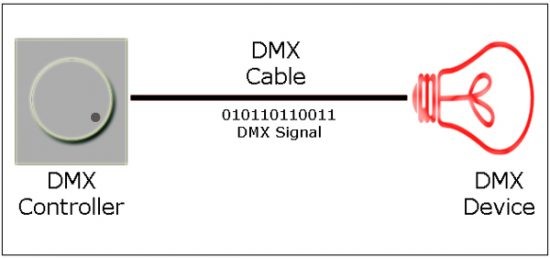
DMX requires different components to work. DMX control is usually achieved with a DMX controller/console, and the “addressable” lighting fixtures are usually interlinked with each other (daisy-chained) using DMX cables, usually three- or five-pin XLR. The DMX controller sends DMX values, which is an 8-bit value (between 0 and 255) corresponding to a 0% to 100% intensity. In DMX512, strings of 512 values are sent 40 times per second, and the location of a DMX value is referred to as the “address.” By addressing the DMX device, it knows which DMX value to use.
“DMX512” stands for Digital Multiplex 512, meaning that 512 channels are controlled digitally through a single data cable. The “address” is the location in the 512-channel DMX universe where the DMX device begins (most DMX lighting fixtures have a series of DIP switches to set the desired device addresses). The “DMX universe” is the 512 channels of output from the DMX controller/console. When we complete the first universe of 512 (DMX A), we should move over to the second universe (DMX B). Note that universes can’t be combined because each needs its own DMX cable run. Regarding DMX512 limitations, one rule in practice is that we can’t have more than 30 devices on one DMX cable run (1,800 feet on paper). After this, the signal needs to be boosted with a proper DMX booster.
As stated earlier, DMX control is usually achieved with a standard DMX controller/console. But it is also popular with DMX software connected with a DMX USB interface (PC-based console) that converts USB output to DMX output.
The standard DMX control cable is an RS-485 “shielded twisted-pair” cable with three connections: two signals (DATA+, DATA–) and a ground (GND). The DATA+ and DATA– signal create the actual DMX signal, while GND is for reference (and to prevent interference). To create a stable DMX signal, the end of each DMX line should be terminated with a 120-Ω resistor wired between the DATA+ and DATA– signals. Recommended DMX connectors are RJ45 and Neutrik XLR five pin. In RJ45, Pin 1 is DATA+, Pin 2 is DATA–, and Pin 7 (and 8) is GND, while Pin 1 of XLR is GND, Pin 2 is DATA–, and Pin 3 is DATA+.

A few (but not all) DMX key points:
DMX is a special language in which a DMX controller talks to DMX luminaries.
A DMX controller sends 8-bit DMX values.
The location of a DMX value is referred to as the address.
By addressing a DMX device, it knows which DMX value to use.
Most DMX devices use more than one DMX address (for example, RGB LED lights).
One DMX line can control 170 individual RGB LED devices.
The DMX topology is serial, and DMX is based on RS-485 communication.
At the data level, a DMX512 controller sends asynchronous data at 250,000 baud (1 start bit, 8 data bits, 2 stop bits, and no parity check).
The communications method entails sending bytes of data in a stream of 8 bits per byte, wrapped around a start bit and stop bits. The start bit is a single-bit period set to logic zero. The stop bits, when using DMX, are two bits set to logic 1. The combination of 1 start bit, 8 bits in the byte, and the 2 stop bits (a total of 11 bits) is called the frame.
It is possible to split a DMX line and boost a DMX signal.
DMX termination (end of line) is very important.
The Digital Multiplex (DMX) protocol is everywhere in lighting, so if you’re fiddling with lighting, it’s not going to be long before you start to have questions about the versatile lighting control protocol, which allows you to have ultimate control over your lighting requirements. Presented below is a primer to explain the simplified function of a DMX signal control system.
What is DMX?
DMX was developed by the United States Institute for Theatre Technology (USITT) in 1986 mainly for controlling lighting equipment and accessories in entertainment applications. DMX set the bar for lighting manufacturers to build fixtures that would all be compatible with each other for controlling everything from a single source, thus giving improved freedom and flexibility, especially when it came to creating lighting shows. DMX is, in fact, a very popular protocol in which a DMX controller communicates to DMX luminaries. Nowadays, it is widely used in architectural scene-setting applications as well.
DMX requires different components to work. DMX control is usually achieved with a DMX controller/console, and the “addressable” lighting fixtures are usually interlinked with each other (daisy-chained) using DMX cables, usually three- or five-pin XLR. The DMX controller sends DMX values, which is an 8-bit value (between 0 and 255) corresponding to a 0% to 100% intensity. In DMX512, strings of 512 values are sent 40 times per second, and the location of a DMX value is referred to as the “address.” By addressing the DMX device, it knows which DMX value to use.
“DMX512” stands for Digital Multiplex 512, meaning that 512 channels are controlled digitally through a single data cable. The “address” is the location in the 512-channel DMX universe where the DMX device begins (most DMX lighting fixtures have a series of DIP switches to set the desired device addresses). The “DMX universe” is the 512 channels of output from the DMX controller/console. When we complete the first universe of 512 (DMX A), we should move over to the second universe (DMX B). Note that universes can’t be combined because each needs its own DMX cable run. Regarding DMX512 limitations, one rule in practice is that we can’t have more than 30 devices on one DMX cable run (1,800 feet on paper). After this, the signal needs to be boosted with a proper DMX booster.
As stated earlier, DMX control is usually achieved with a standard DMX controller/console. But it is also popular with DMX software connected with a DMX USB interface (PC-based console) that converts USB output to DMX output.
The standard DMX control cable is an RS-485 “shielded twisted-pair” cable with three connections: two signals (DATA+, DATA–) and a ground (GND). The DATA+ and DATA– signal create the actual DMX signal, while GND is for reference (and to prevent interference). To create a stable DMX signal, the end of each DMX line should be terminated with a 120-Ω resistor wired between the DATA+ and DATA– signals. Recommended DMX connectors are RJ45 and Neutrik XLR five pin. In RJ45, Pin 1 is DATA+, Pin 2 is DATA–, and Pin 7 (and 8) is GND, while Pin 1 of XLR is GND, Pin 2 is DATA–, and Pin 3 is DATA+.
A few (but not all) DMX key points:
DMX is a special language in which a DMX controller talks to DMX luminaries.
A DMX controller sends 8-bit DMX values.
The location of a DMX value is referred to as the address.
By addressing a DMX device, it knows which DMX value to use.
Most DMX devices use more than one DMX address (for example, RGB LED lights).
One DMX line can control 170 individual RGB LED devices.
The DMX topology is serial, and DMX is based on RS-485 communication.
At the data level, a DMX512 controller sends asynchronous data at 250,000 baud (1 start bit, 8 data bits, 2 stop bits, and no parity check).
The communications method entails sending bytes of data in a stream of 8 bits per byte, wrapped around a start bit and stop bits. The start bit is a single-bit period set to logic zero. The stop bits, when using DMX, are two bits set to logic 1. The combination of 1 start bit, 8 bits in the byte, and the 2 stop bits (a total of 11 bits) is called the frame.
It is possible to split a DMX line and boost a DMX signal.
DMX termination (end of line) is very important.